Section 4: Bubble Diagrams
In the previous section, I briefly discussed the relationship between spaces. The spacial relationship of areas and rooms within a building is paramount to a buildings functionality, aesthetic qualities, cost, buildability and general comfort and therefore should be rigorously worked on in conjunction with the client and their desires. The ultimate goal is to create the barebones of a bubble diagram, whereby the spacial relationships between various areas and the required circulation routes between said areas are clearly defined, therefore allowing the designer to initiate the production of schematic layouts. This is the single most important transition in any construction project, as it defines every single part of the building when finalised, meritting the allocation of ones time and effort.
To illustrate the progression from the clients desired layout to the finalised bubble diagram visually depicting these relationships, including the circulatory routes between the various areas, I have included some examples from a very early project of mine, as follows:
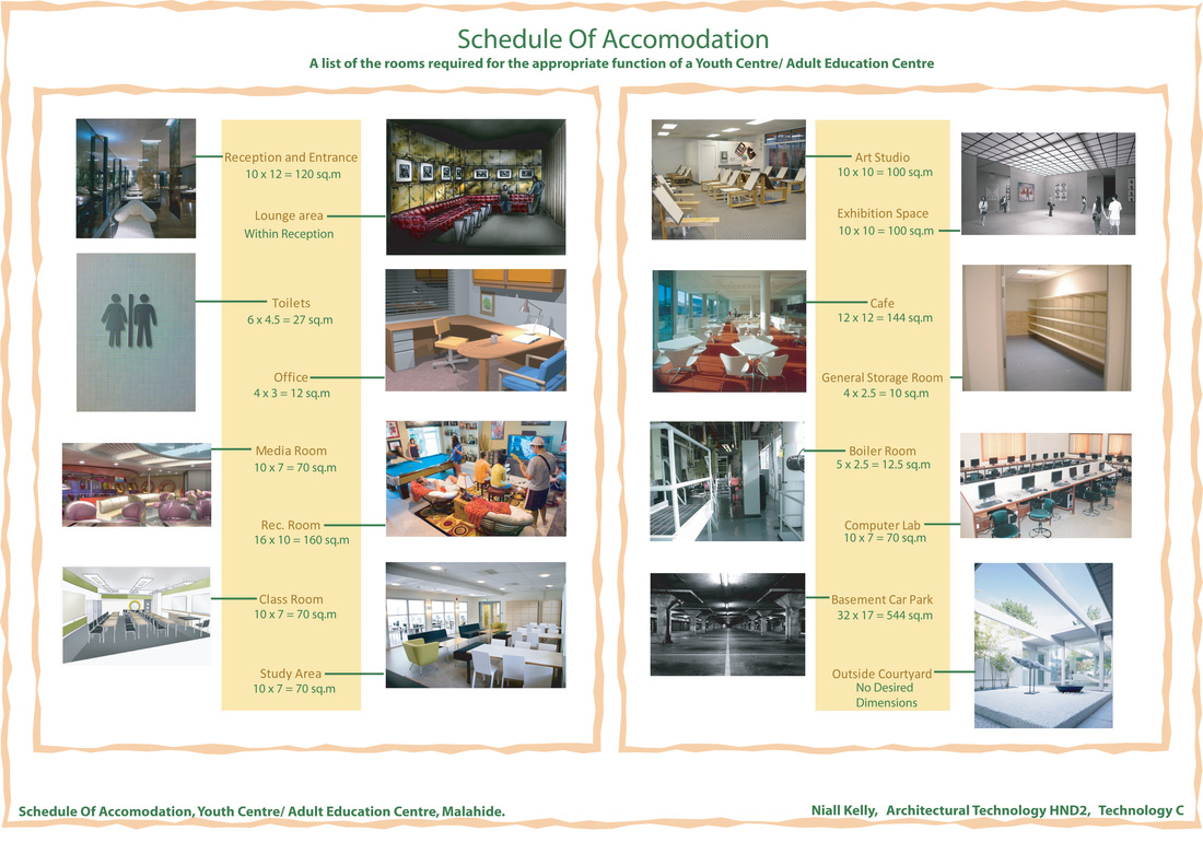
STEP 1: The First Step is to ascertain a full schedule of accommodation. This will require you to interface with your clients at an early stage to discuss the buildings use as well as any special requirements the client may have. You will then begin to compile a complete schedule accommodation with the client which is dependent on the buildings use and the clients wishes. You must be informative at this stage of the process, explaining all positives and negatives which their desires may create, as well as discuss technical difficulties which may be faced due to site constrictions, local authorities requirements, building regulations, CDM regulations, cost escalation etc. To be informative, honest and proactive with the client at this stage will help to avoid any possible conflicts during construction, as the client understands the constraints in which the proposed project may be bound. It also helps to build and honest and approachable relationship between you and the client, as they see you are a straight forward, factual and professional individual. The below image depicts a complete schedule of accommodation for one of my early projects, which also informs of the minimum requirements for each spaces individually allocated floor areas, which are both dependent on building regulations, metric handbook guidelines as well as the clients wishes.
To illustrate the progression from the clients desired layout to the finalised bubble diagram visually depicting these relationships, including the circulatory routes between the various areas, I have included some examples from a very early project of mine, as follows:
STEP 1: The First Step is to ascertain a full schedule of accommodation. This will require you to interface with your clients at an early stage to discuss the buildings use as well as any special requirements the client may have. You will then begin to compile a complete schedule accommodation with the client which is dependent on the buildings use and the clients wishes. You must be informative at this stage of the process, explaining all positives and negatives which their desires may create, as well as discuss technical difficulties which may be faced due to site constrictions, local authorities requirements, building regulations, CDM regulations, cost escalation etc. To be informative, honest and proactive with the client at this stage will help to avoid any possible conflicts during construction, as the client understands the constraints in which the proposed project may be bound. It also helps to build and honest and approachable relationship between you and the client, as they see you are a straight forward, factual and professional individual. The below image depicts a complete schedule of accommodation for one of my early projects, which also informs of the minimum requirements for each spaces individually allocated floor areas, which are both dependent on building regulations, metric handbook guidelines as well as the clients wishes.
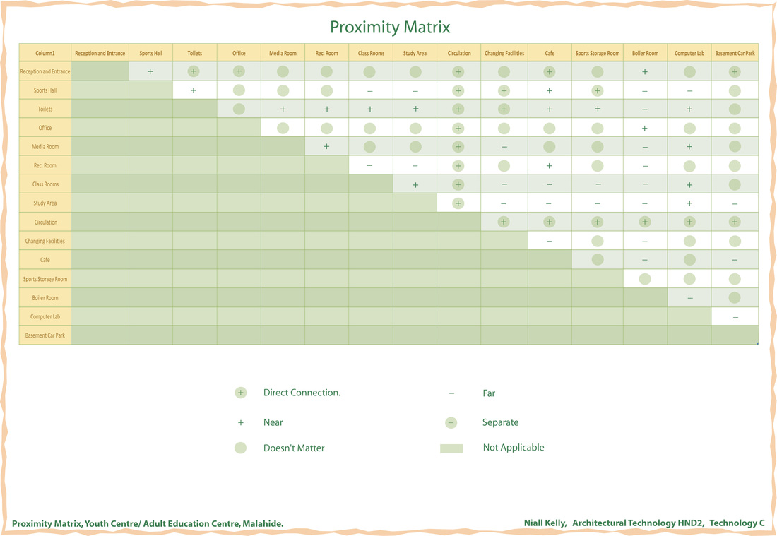
STEP 2: The second step is to compile the information gathered from interfacing with the client as well as cross checking building regulations into a visual diagram whereby the relationships between the various spaces are clearly depicted. This is primarily to aid the designer in their bubble diagram creation as the designer can visually see the relationships which were previously ascertained with the client, which makes the whole design process more fluid and conflict free. The simplest form of diagram which illustrates the spacial relationships of the proposed building is a Proximity Matrix, whereby a series of icons have preset meanings, therefore allowing for the easy comprehension of the required spacial relationships. The Proximity Matrix should always be shown to the client before further design work is carried out. This is quite simply a means of achieving some final clarification of the clients desired spacial relationships, and will reduce the possibility for conflict at a later stage. Below is an example of a Proximity Matrix, whereby the clients desires as well as regulation allowable spacial relationships are depicted in a concise manner.
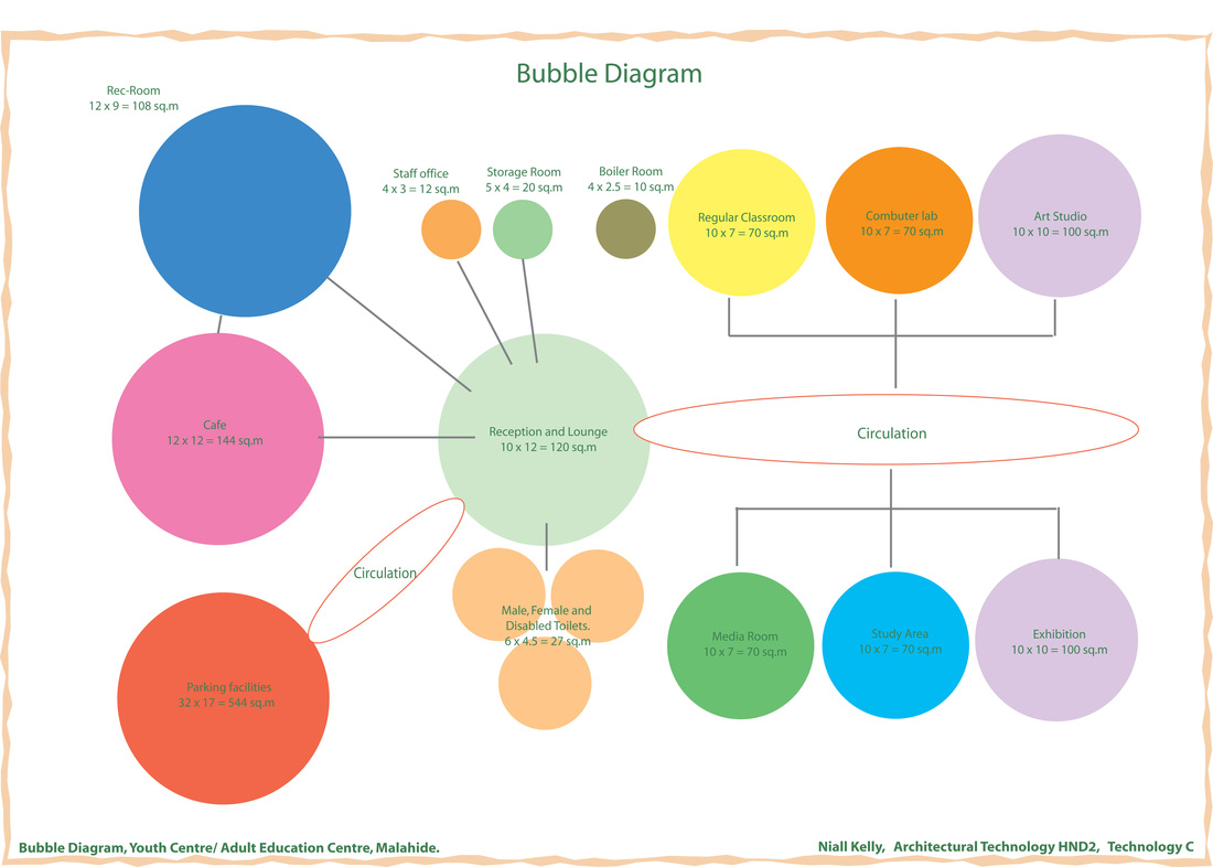
STEP 3: Once the proximity Matrix is generated, you should be able to quickly and easily develop numerous possible bubble diagrams to illustrate the relationship of the various spaces within the building. Typically, I find it good practice to colour code the various spaces, so that I can then use area and volumetric diagrams of the same colour schemes to initiate the conceptual design stage by moving and stacking the individual spaces to coincide with the clients desired bubble diagram layout. Below is an example of a Bubble Diagram which has colours assigned to the various spaces, as well as shows circulation and connections between the various rooms. The below Bubble Diagram adheres to the constraints defined by the above proximity matrix.